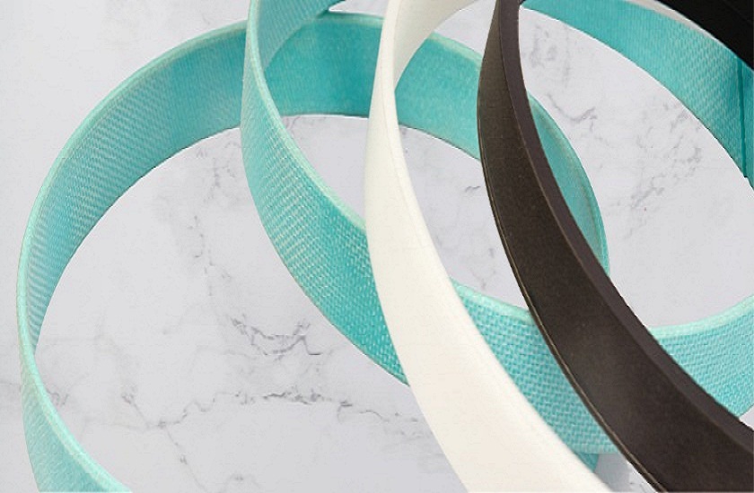
Guide And Back Up Rings
Guide rings are mounted on the piston and piston rod of a hydraulic cylinder and to absorb the side loads and also to prevent metal to metal contact between the sliding parts liked Rod and Gland / Piston and Bore .
Non-metallic guide rings offer major benefits compared with the traditional metallic guides :
Guide Rings are available in several materials: Most commonly used are:
Design of Guide rings :
To chose the correct size of Guide ring and also the number of guide rings required the following formula can be used as a guide to get a rough estimate :
Load Bearing width = Fxf / dxPr
Material Description Max Load bearing capacity Surface Speed Uses Bronze filled PTFE tapes (BFT) 15 N/mm2 15 m/s Low to medium duty with limited radial forces Machined Acetal guides 25 N/mm2 1 m/s Medium to heavy duty Phenolic bonded resin tapes (PBR) ( with solid PTFE lubricants ) 75 N/mm2 1 m/s With fabric composite for heavy duty and high radial forces
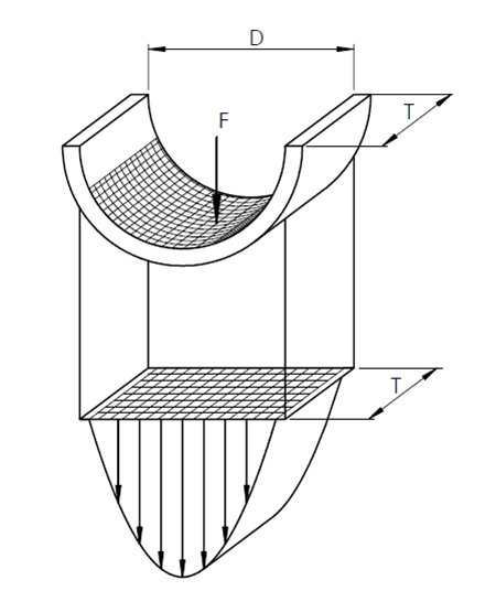
Load Distribution diagram
The values for the load on the Guide ring are valid for a load distribution as illustrated in following fig . The flexibility of the materials ensures a relatively constant specific load , irrespective of the size of the radial forces F , as with increasing radial loading, the guide surface subjected to the load increases also .
The radial forces which occur can vary within wide ranges and cannot always be calculated exactly in advance . For such cases , a safety factor of at least 2 is recommended .
Bronze filled PTFE tapes
BFT tapes are used as piston and rod guides due to their outstanding friction behavior , stick-slip free running and good resistance to high temperatures and chemicals . BFT tapes are available in running length . BFT tapes have a rectangular cross-section and are chamfered at the edges for easy installation into the grooves .
Advantages
color Groove Width Strip Width Strip Thickness Brown 5.7 5.6 2.5 Brown 6.3 6.1 2.5 Brown 8.1 8 2.5 Brown 9.7 9.5 2.5 Brown 15 14.8 2.5 Brown 20 19.8 2.5 Brown 25 24.8 2.5 Brown 20 19.8 3 Brown 25 24.8 3 Brown 30 29.8 3
color Groove Width Strip Width Strip Thickness Green 5.7 5.6 2.5 Green 6.3 6.1 2.5 Green 8.1 8 2.5 Green 9.7 9.5 2.5 Green 15 14.8 2.5 Green 20 19.8 2.5 Green 25 24.8 2.5 Green 20 19.8 3 Green 25 24.8 3 Green 30 29.8 3
Phenolic bonded resin tapes (PBR)
Phenolic bonded resin tapes (PBR) of fabric reinforced composite materials with PTFE lubricants are used in hydraulic cylinders exposed to high loads that can occur e.g . in mobile hydraulics and presses . The high compressive strength , good sliding behavior and the exceptional wear resistant properties ensure a long service life .
Phenolic bonded resin tapes (PBR) . They are available in running length which can be cut to size to match the bore or rod guiding area .
Advantages
Our customers
Client 6

Client 3

Client 4

Client 2

Client 3

Client 1

Client 4

Client 6

Client 1

Client 2
